
ISTEC CORPORATION
Flow Measurement & Control
5 Park Lake Road, Unit 6
Sparta, NJ 07871 USA
Tel 973-383-9888
Fax 973-383-9088
Email
![]()
Newsletter Sign-up Here
OFFICE HOURS
We will be closed on May 24th and May 27th, 2019 in observation of Memorial Day.
We will open again on Tuesday May 28th, 2019
Remember our troops in your prayers as they keep us safe on this Memorial Day.
We Accept
![]()
Last Update:
1800 Series Water Meter
 ISTEC’s 1800 Series water meters are ideal for water metering and performance verification applications. These hardy meters are also suitable for condensation application up to 248°F and 232 psi. We stock from 1/2" through 6" meters (with up t o 12" as special order) and all come standard with a pulse output.
Multi-Jet |
|

| Model No. | 1807 OBSOLETE |
1810 |
1811 OBSOLETE |
1812 OBSOLETE |
1815 |
1816 OBSOLETE |
1820 OBSOLETE |
| Pipe Size | 3/4" |
1" |
1" |
1" |
1-1/2" |
1-1/2" |
2" |
| Minimum Flow Rate (gpm) | 0.22 |
0.4 |
0.4 |
0.4 |
0.7 |
0.7 |
2.64 |
| Continuous Flow Rate (gpm) | 11 |
26.4 |
26.4 |
26.4 |
44 |
44 |
66 |
| Maximum Flow Rate (gpm) | 22 |
52.8 |
52.8 |
52.8 |
88 |
88 |
132 |
| Maximum Operation Temperature (°F) | 248 |
248 |
248 |
248 |
248 |
248 |
248 |
| Maximum Operation Pressure (psi) | 232 |
232 |
232 |
232 |
232 |
232 |
232 |
| Design | Multi-Jet |
||||||
| Mounting Connections | NPT |
NPT |
NPT |
NPT |
NPT |
NPT |
Flanged |
| Mounting Position | U |
H |
D |
U |
H |
D |
H |
| Pulse (gal/pulse) | 1 |
1 |
1 |
1 |
1 |
1 |
10 |
| Weight (lbs) | 5.25 |
7.5 |
8.1 |
8.1 |
14.2 |
15.5 |
27.5 |
| Dimensions | 1807 OBSOLETE |
1810 |
1811 OBSOLETE |
1812 OBSOLETE |
1815 |
1816 OBSOLETE |
1820 OBSOLETE |
Pipe Size |
3/4" |
1" |
1" |
1" |
1-1/2" |
1-1/2" |
2" |
A |
3-1/4" |
2" |
3-3/4" |
3-3/4" |
2-1/4" |
4-3/4" |
3-1/4" |
B |
6-1/2" |
7" |
7-1/4" |
7-1/4" |
8" |
8-1/4" |
6-1/4" |
C |
4-1/4" |
10-1/4" |
6" |
6" |
11-7/8" |
8" |
10-1/2" |
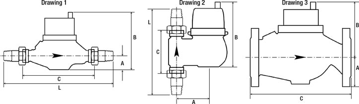
Drawing |
2 |
1 |
2 |
2 |
1 |
2 |
3 |
PRESSURE LOSS


ACCURACY FLOW RATE

Woltmann Design |
|

| Model No. | 1825 |
1830 |
1835 |
1840 |
| Pipe Size | 2" |
3" |
4" |
6" |
| Minimum Flow Rate (gpm) | 2.6 |
14.1 |
8.8 |
35 |
| Continuous Flow Rate (gpm) | 66 |
140.9 |
264 |
880.6 |
| Maximum Flow Rate (gpm) | 264 |
396.3 |
792.5 |
1320.9 |
| Maxim Operating Temperature (°F) | 248 |
248 |
248 |
248 |
| Maximum Operating Pressure (psi) | 232 |
232 |
232 |
232 |
| Design | Woltman |
Woltman |
Woltman |
Woltman |
| Mounting Connections | Flanged |
Flanged |
Flanged |
Flanged |
| Mounting Position | Horz or Vert |
Horz or Vert |
Horz or Vert |
Horz or Vert |
| Pulse (gal/pulse) | 10 |
10 |
10 |
100 |
| Weight (lbs) | 25 |
31 |
48 |
88 |

Dimensions |
1825 |
1830 |
1835 |
1840 |
Pipe Size |
2" |
3" |
4" |
6" |
A |
5-1/2" |
5-1/2" |
8-1/4" |
9" |
B |
3" |
3-3/4" |
4-3/8" |
5-3/4" |
C |
7-7/8" |
8-7/8" |
9-7/8" |
11-7/8" |
PRESSURE LOSS

ACCURACY FLOW RATE

INSTRUCTIONS
- Before beginning the installation, verify that the system temperature, pressure and flow rate do not exceed the ratings indicated on the meter.
- The meter is designed to operate at a sustained flow of 1/2 the Maximum Flow Rating (indicated as the Continuous Flow Rating). The meter should not be operated at the Maximum Flow Rating for more than one hour per day as excessive wear and/or failure will result.
- Flush the pipeline thoroughly after any plumbing changes to eliminate the possibility of foreign materials reaching the meter.
- The 1/2" and 3/4" meters may be installed in horizontal or vertical pipelines (either up or down flow). To achieve the rated accuracy, the meter should be the same diameter as the pipe and there should be at least five (5) pipe diameters of straight pipe before and after the meter. The 1" through 2"meters have a specific flow orientation and must be installed accordingly. There is no straight pipe requirement before or after the 1" through 2" (1820 only) meters. The 2" (1825 only) and larger meters may be installed horizontally or vertically and require at least five (5) pipe diameters of straight pipe before and after the meter. In horizontal installations, the flow counter should be facing straight upward.
- Pay careful attention to the flow direction as indicated by the arrow cast into the meter body.
- It is highly recommended that a strainer be installed upstream of the meter inlet. It is also recommended that a shutoff valve be located before and after the meter to facilitate service.
- Care should be taken to protect the meter from water hammer as well as freezing temperatures.
- The counter is calibrated in U.S. gallons and cannot be reset. It will roll around to zero after reaching its maximum reading.
- All 1800 Series meters are equipped with a pulse output (magnetically driven "dry contact type" reed switch). Each contact closure is equal to one (1), ten (10) or one hundred (100) gallons of water as indicated on the meter. The electrical rating of the switch is 0.2 amps at 24 volt.
HOW TO READ AN 1800 SERIES WATER METER
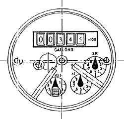
The 1800 Series counter consists of a row of numbers (roller counter) and one or more circular dials with rotating pointers. There is also a star shaped wheel that rotates whenever flow is present (trickle indicator).
The roller counter is calibrated in U.S. gallons and cannot be reset. It indicates the total flow through the meter in gallons, hundreds of gallons, thousands of gallons, etc. The correct multiplier is indicated on the face adjacent to the roller counter. In the example above, the amount indicated is 345 x 100 or 34,500.
The circular dials indicate tenths of gallons, gallons, tens of gallons, etc. The respective multiplier is marked adjacent to the dial. For example, on the dial marked "x10", each number represents increments of ten gallons (i.e., 3 = 30 gallons, etc.) and one full rotation equals 100 gallons. On the dial marked "x0.1", each increment is one tenth (1/10) of a gallon (4 = 0.4) and a full rotation of the dial represents a total of 1 gallon. Note that if the pointer is between two numbers, the lower number is read.
The counter will roll around to zero and restart once it reaches its maximum reading.
 Single-Jet |
|
| Model Number | 1800 – OBSOLETE |
1805 – OBSOLETE |
| Pipe Size | 1/2" |
3/4" |
| Minimum Flow Rate (gpm) | 0.13 |
0.22 |
| Vertical Minimum Flow Rate (gpm) | 0.3 |
0.4 |
| Continuous Flow Rate (gpm) | 6.6 |
11 |
| Maximum Flow Rate (gpm) | 13.2 |
22 |
| Maximum Operation Temperature (°F) | 248 |
248 |
| Maximum Operation Pressure (psi) | 232 |
232 |
| Design | Single Jet |
Single Jet |
| Mounting Connections | NPT |
NPT |
| Mounting Position | Horz or Vert |
Horz or Vert |
| Pulse (gal/pulse) | 1 |
1 |
| Weight (lbs) | 2.8 |
3.2 |
Dimensions |
||
| “L1” | 4-1/2" |
5-1/4" |
| “L2” | 9-1/4" |
10-1/4" |
| “H” | 3-3/4" |
3-3/4" |
| “h” | 3/4" |
3/4" |
PRESSURE LOSS

ACCURACY FLOW RATE

Download PDF Version • Download Installation Manual • Download Wiring Diagram