
ISTEC CORPORATION
Flow Measurement & Control
5 Park Lake Road, Unit 6
Sparta, NJ 07871 USA
Tel 973-383-9888
Fax 973-383-9088
Email
![]()
Newsletter Sign-up Here
OFFICE HOURS
We will be closed on May 24th and May 27th, 2019 in observation of Memorial Day.
We will open again on Tuesday May 28th, 2019
Remember our troops in your prayers as they keep us safe on this Memorial Day.
We Accept
![]()
 Aquametro Contoil Oil Meters Overview
Since 1928, the name Aquametro has been synonymous with metering technology – through the many generations of quality products and practical solutions provided. Aquametro is continually aware of the variety of specific requirements needed throughout the world – whether technological, economical, ecological, or cultural, and this determines the way we act. Our closeness to the market is based on our constant readiness to break new ground in our quest for optimum solutions. The experience and skills we have gained in this way are adopted in our daily work by both our operatives in Switzerland and our offices and representatives throughout the world.
FEATURES
|
BENEFITS
|
|
Contoil VZF II 15-50
Contoil VZO 4 - 50
Contoil VZF II / VZOA
VZFA II
VZOA 4 and 8 • Volume Display on Roller Counter VZOA 15-50
|
|
|
|


TECHNICAL DATA1)
 |
Other Versions Available
|
| Type | VZF II 15 |
VZF II 20 |
VZF II 25 |
VZF II 40 |
VZF II 50 |
||
| Nominal Diameter | DN |
mm inch |
15 1/2 |
20 3/4 |
25 1 |
40 1-1/2 |
50 2 |
| Installation length | mm |
165 |
165 |
190 |
300 |
350 |
|
| Nominal Pressure with Threaded Ends Nominal Pressure with Flanges |
PN |
bar |
16 |
16 |
16 |
16 |
16 |
| Maximum Temperature | Tmax |
°C |
130,180 |
||||
| Maximum Flow Rate Nominal Flow Rate Minimal Flow Rate Approx. Starting Flow Rate |
Qmax3) Qcont3) Qmin |
l/h l/h l/h l/h |
600 400 10 4 |
1 500 1 000 30 12 |
3 000 2 000 75 30 |
9 000 6 000 225 90 |
30 000 20 000 750 300 |
| Maximum Permissible Error Repeatability |
±1% of Actual Value ±0.2% |
||||||
| Safety Filter Mesh Size Dirty Filter Mesh Size |
mm mm |
0.400 0.250 |
0.400 0.400 |
0.400 0.400 |
0.800 0.600 |
0.800 0.600 |
|
| Volume of Measuring Chamber | approx.cm3 |
12 |
36 |
100 |
330 |
1 200 |
|
| Housing Finish | Enameled Red RAL 3013 |
||||||
| Weight with Threaded Ends Weight with Flanges PN 25 |
approx. kg approx. kg |
2.2 3.8 |
2.5 4.5 |
4.2 7.5 |
17.3 20.3 |
– 41.0 |
|
| Smallest Readable Amount: Total Volume Resettable Volume Digital Flow Rate Display Registration Capacity |
l, m3 l, m3 l/h l, m3 |
No Decimal Places 1 Decimal Place 1 Decimal Place 8 Digits |
|||||
| Registration Time at Qcont until Overrunning to Zero | H |
128 000 |
100 000 |
50 000 |
16 667 |
5 000 |
|
| Outputs3 Pulse Value for Totalizer Current 4 - 20mA for Flow Rate Frequency for Flow Limiting Switch |
Vol./pulse I4 /Q1, I20 Q2 f1/Q1, f2/Q2 Qmin, Qmax |
Pulse Value and Width Parameterizable Flow Rates to 4 and 20mA Parameterizable Frequency and Flow Rate Parameterizable Minimum, Maximum and Hysteresis Parameterizable |
|||||
1) Manufacturer's specification, valid for the reference conditions as specified under Meter Data
2) 1 U.S. gallon corresponds to 3.785 liters
3) For burners and engines or motors, the meter must be selected on the basis of the permanent flow rate. For higher viscosities, or if the meter is installed on the suction side, the pressure drop and any reduction in the measuring
range must be taken into consideration.
4) Weight without couplings.
5) Two freely selectable outputs are available, totally independent of each other.
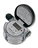
ELECTRONIC DISPLAY
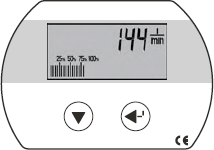 |
Display Values: |
|
Display: |
|
|
Temperature: |
|
|
Safety: |
|
|
Power Supply: |
|
|
Data Preservation: |
|
|
Protection Class: |
|
OUTPUTS
Four different output functions are available -
- Pulser for volume pulses with programmable pulse value (for external totalizer)
- Analog current output 4-20mA corresponding to flow rate
- Frequency output 0-100Hz corresponding to flow rate
- Switching function (limiting value switch) specified by programmable upper and lower flow rates
Except for the current output function, any two of the remaining three functions can always be used simultaneously. This results in two types of connection:
| 1 Potential-free Digital Output (Rel. 1), Parameterizes to one of the three functions described below. | 2 Potential-free Digital Outputs (Rel. 1 + Rel. 2), each Parameterizes to one of the three functions described below. |
| 1 Passive Analog 4-20mA Output also used for Powering the meter. | The Analog Output is not available in this case. The Power, however, is suppled over these terminals. |
 |
 |
SPECIFICATION OF THE OUTPUTS
Passive Analog Output (1-2)
| Voltage Range U: | 6-30V DC |
| Maximum Load RL: | (U-5) V / 0.0215A [Ω] |
| Resolution: | 16-bit |
| Maximum Error: | ± 0.2mA |
| Update Interval: | <1 s |
Digital Outputs (3-4, 5-6)
| Maximum Voltage Umax: | 48V AC/DC |
| Maximum Current Imax: | 50mA |
| Maximum Output Frequency fmax: | 100Hz |
| Update Interval: | <1 s |
| ON-Resistance R0: | ≤100Ω |
| OFF-Resistance R∞: | ≥10 MΩ |
| Insulation Voltage: | ≥100V AC/DC |
ADJUSTABLE FUNCTIONS
Volume Pulses
| Pulse Width t: | 5, 50, 250, 500ms | 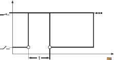 |
| Pulse Value: | Parameterizable |
Current Signal
| Flow Rate at 4mA Q1: | Parameterizable |  |
| Flow rate 20mA Q2: | Parameterizable | |
| Attenuation: | Parameterizable |
Frequency Signal
| Output Frequency fmax: | 100Hz |  |
| Pulse ratio: | 1:1 | |
| Frequency / Flow Rate f1/Q1: | Parameterizable | |
| Frequency / Flow Rate f2/Q2 : | Parameterizable |
Limiting Value Switch
| Limit Qmin | Parameterizable |  |
| Limit Qmax : | Parameterizable | |
| Hysteresis H: | Parameterizable |
DIMENSIONS
| Type | mm |
VZF II 15 |
VZF II 20 |
VZF II 25 |
VZF II 40 |
VZF II 50 |
 |
Length |
165 |
165 |
190 |
300 |
350 |
Width |
105 |
105 |
130 |
210 |
280 |
|
Height |
155 |
164 |
191 |
243 |
299 |
Detailed Dimensional Drawings in Meter Data
TYPE DESIGNATION KEY

ORDERING SPECIFICATIONS
| Threaded ends, PN 16 | Type 130°C |
Order No. |
||
 |
VZF II 15 RC 130/16 |
93705 |
||
VZF II 20 RC 130/16 |
93708 |
|||
VZF II 25 RC 130/16 |
93725 |
|||
VZF II 40 RC 130/16 |
93730 |
|||
| Flanges, PN 25 | Type 180°C |
Order No. |
||
 |
VZF II 15 FL 130/25 |
93706 |
||
VZF II 20 FL 130/25 |
93709 |
VZF II 20 FL 180/25 |
93710 |
|
VZF II 25 FL 130/25 |
93726 |
VZF II 25 FL 180/25 |
93727 |
|
VZF II 40 FL 130/25 |
93731 |
VZF II 40 FL 180/25 |
93732 |
|
VZF II 50 FL 130/25 |
93735 |
VZF II 50 FL 180/25 |
93736 |
|
| Modification VZF II | For Marine Type Approval (e.g., GL, LRS, DNV) | 96295 |
||
TECHNICAL DATA1)
 |
Option: Reed Pulser 48V |
| Type | VZO 4 Qmin 0.5 |
VZO 4 |
VZO 8 |
|||
| Nominal Diameter | mm inch |
4 1/8 |
4 1/8 |
8 1/4 |
||
| Connection Threads of Meter | inch |
1/8 |
1/8 |
1/4 |
||
| Nominal Pressure | bar |
25 |
||||
| Temperature | Tmax |
°C |
60 |
|||
| Maximum Flow Rate Nominal Flow Rate Minimal Flow Rate Approx. Starting Flow Rate |
Qmax3) Qcont3) Qmin4) |
l/h l/h l/h l/h |
40 25 0.5 0.3 |
80 50 1 0.4 |
200 135 4 1.6 |
|
| Maximum Permissible Error Repeatability |
±1% of Actual Value4) ±0.2% |
|||||
| Smallest Readable Amount: Registration Capacity: Registration at Qcont until Overrun to Zero |
l m3 h |
0.001 100 4 000 |
0.001 100 2 000 |
0.01 1 000 7 400 |
||
| Safety Filter Mesh Size Dirty Filter Mesh Size |
mm mm |
0.125 0.080 |
0.125 0.080 |
0.150 0.100 |
||
| Volume of Measuring Chamber | approx.cm3 |
5 |
5 |
12.5 |
||
| Weight without Couplings | approx. kg |
0.65 |
0.65 |
0.75 |
||
| Reed Pulsers | RE 1 RE 0.1 RE 0.00125 RE 0.00311 |
l/ pulse |
– – – – |
– 0.1 0.00125 – |
1 – – 0.00311 |
|
| Pulse Frequency for | RE 0.001255) |
at Qmax at Qmin |
Hz Hz |
– – |
17.777 0.222 |
– – |
| Pulse Frequency for | RE 0.003115) |
at Qmax at Qmin |
Hz Hz |
– – |
– – |
17.864 0.357 |
1) Manufacturer's specification, valid for the reference conditions as specified under Meter Data
2) 1 U.S. gallon corresponds to 3.785 liters
3) For burners and engines or motors, the meter must be selected on the basis of the permanent flow rate. For higher viscosities, or if the meter is installed on the suction side, the pressure drop and any reduction in the measuring
range must also be taken into consideration.
4) Max. permissible error: VZO 4 Qmin 0.5: 0.5 l/h - 2 l/h = + 1% /– 2%. VZO 4: 1 l/h - 2 l/h = + 1% /– 2%
5) Note: pulses of short duration!
VZOA 4 and 8 with EEC Legal Verification D 04/5.232.14
| Data According to Type Approval Specifications | VZOA 4 |
VZOA 8 |
||
| Temperature max. | Tmax |
°C |
50 |
50 |
| Maximum Flow Rate | Qmax |
l/h |
20 |
140 |
| Nominal Flow Rate | Qcont |
l/h |
20 |
140 |
| Minimal Flow Rate | Qmin |
l/h |
2 |
14 |
| Max. Permissible Error | ±% of Actual Value |
0.5 |
0.3 |
|
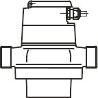
DIMENSIONS in mm

Detailed Dimensional Drawings in Meter Data
MOUNTING KIT for VZO 8

RE PULSERS
 |
Switching Element: | Reed Switch with Dry Contact (inert gas) | |
| Switching Voltage: | Max. 48V AC/DC, Protection Class III (SELV) | ||
| Switching Current: | Max. 50mA | ||
| Quiescent Current: | Open Contact | ||
| Switching Power: | Max. 2 W | ||
| ON-time: | VZO 4-RE 0.00125: | 30-70% (17-39ms bei 80 l/h) | |
| VZO 4-RE 0.1: | 40-60% | ||
| VZO 8-RE 0.00311: | 30-70% (17-39ms bei 200 l/h) | ||
| VZO 8-RE 1: | 40-60% | ||
| Temperature: | Ambient -10 - +60°C | ||
| Protection Class: | IP 50 (IEC 60529) against Harmful Dust Deposits – Option: IP 54 additional against Splashing Water |
||
| Connections: | On Plug Connector with Cable, 3, 5 - 5mm Ø | ||
ORDERING SPECIFICATIONS
 |
Type |
Order No. |
Type |
Order No. |
VZO 4 |
92680 |
VZO 8 |
92630 |
|
VZO 4 RE 0.00125 |
89763 |
VZO 8 RE 0.00311 |
89733 |
|
VZO 4 RE 0.1 |
89761 |
VZO 8 RE 1 |
89731 |
|
VZO 4 Qmin 0.5 |
92678 |
|||
VZOA 4 |
93668 |
VZOA 8 |
93669 |
|
| Modification | Increased Protection (IP 54) |
80368 |
||
Special Versions with FPM Fluoroelastomer Gaskets
VZO 4 V – Order No. 92487
VZO 4 V – RE 0.1 Order No. 92489
TECHNICAL DATA1)
 |
|
| Type | VZO 4 OEM |
VZO 8 OEM |
|||
| Nominal Diameter | mm inch |
4 1/8 |
8 1/4 |
||
| Connection Threads of Meter | inch |
1/8 |
1/4 |
||
| Nominal Pressure | bar |
32 |
25 |
||
| Temperature | Tmax |
°C |
60 |
60 |
|
| Maximum Flow Rate Nominal Flow Rate Minimal Flow Rate Approx. Starting Flow Rate |
Qmax2 Qcont2 Qmin3 |
l/h l/h l/h l/h |
80 50 1 0.4 |
200 135 4 1.6 |
|
| Maximum Permissible Error Repeatability |
±1% of Actual Value4) ±0.2% |
||||
| Safety Filter Mesh Size Dirty Filter Mesh Size |
mm mm |
– 0.080 |
0.150 0.100 |
||
| Volume of Measuring Chamber | approx.cm3 |
5 |
12.5 |
||
| Weight | approx. kg |
0.65 |
0.75 |
||
| Reed Pulsers | RE |
l/pulse |
0.005 |
0.0125 |
|
| Pulse Frequency | at Qmax at Qmin |
Hz Hz |
4.444 0.056 |
4.444 0.089 |
|
1) Manufacturer's specification, valid for the reference conditions as specified under Meter Data
2) For burners and engines or motors, the meter must be selected on the basis of the permanent flow rate. For higher viscosities, or if the meter is installed on the suction side, the pressure drop and any reduction in the measuring
range must also be taken into consideration.
3) Max. permissible error: VZO 4 OEM: 1 l/h - 2 l/h = +1% / –2%
SAFETY PRECAUTION
When connecting the Reed pulser to a low-voltage power source (50 - 250V AC/DC), the specialist installing the equipment is responsible for ensuring that all local regulations are observed (e.g., regulations for electrical installations, personnel safety).
DIMENSIONS in mm

RE PULSERS
|
Switching Element: | Reed Switch with Dry Contact (inert gas) | |
| Switching Voltage: | Max. 230V AC/DC | ||
| Switching Current: | Max. 50mA | ||
| Quiescent Current: | Open Contact | ||
| Switching Power: | Max.3 VA | ||
| ON-time: | 40-55% | ||
| Temperature: | Ambient -10 - +60°C | ||
| Protection Class: | IP 50 (IEC 60529) against Harmful Dust Deposits | ||
| Connections: | Cable Cross Section 2 x 0.5mm2, Length 480mm | ||
REMOTE TOTALIZER for VZO 4 OEM
 |
Power Supply: | 230V, 50/60Hz | |
| Pulse Value (input): | 0.005 l | ||
| Smallest Readable Amount: | 0.005 l | ||
| Registration Capacity: | 10 000 l | ||
| Registration: | at Q before Return to Zero 200 h | ||
| ON-time: | 40-55% | ||
| Panel Cut-out: | 27 x 14.4 – 0 / +0.2mm | ||
| Installation Depth: | 56mm | ||
ORDERING SPECIFICATIONS
Type |
Description |
Order No. |
|
 |
VZO 4 OEM-RE 0.005 |
Version for OEMs |
89765 |
Remote Totalizer for VZO 4 OEM |
93349 |
||
VZO 8 OEM-RE 0.0125 |
Version for OEMs |
89771 |
TECHNICAL DATA1)
 |
Option: Reed Pulser or RV / IN Pulser Other Versions Available
|
| Type | VZF II 15 |
VZF II 20 |
VZF II 25 |
VZF II 40 |
VZF II 50 |
||
| Nominal Diameter | DN |
mm inch |
15 1/2 |
20 3/4 |
25 1 |
40 1-1/2 |
50 2 |
| Installation Length | mm |
165 |
165 |
190 |
300 |
350 |
|
| Nominal Pressure with Threaded Ends Nominal Pressure with Flanges |
PN PN |
bar bar |
16 25, 40 |
||||
| Maximum Temperature | Tmax |
°C |
130,180 |
||||
| Maximum Flow Rate Nominal Flow Rate Minimal Flow Rate Approx. Starting Flow Rate |
Qmax3) Qcont3) Qmin |
l/h l/h l/h l/h |
600 400 104) 4 |
1 500 1 000 30 12 |
3 000 2 000 75 30 |
9 000 6 000 225 90 |
30 000 20 000 750 300 |
| Maximum Permissible Error Repeatability |
±1% of Actual Value ±0.2% |
||||||
| Safety Filter Mesh Size Dirty Filter Mesh Size |
mm mm |
0.400 0.250 |
0.400 0.400 |
0.400 0.400 |
0.800 0.600 |
0.800 0.600 |
|
| Volume of Measuring Chamber | approx.cm3 |
12 |
36 |
100 |
330 |
1 200 |
|
| Housing Finish | Enameled Red RAL 3013 |
||||||
| Weight with Threaded Ends5) Weight with Flanges PN 25 Weight with Flanges PN 40 |
approx. kg approx. kg approx. kg |
2.2 3.8 4.4 |
2.5 4.5 5.5 |
4.2 7.5 7.8 |
17.3 20.3 20.5 |
– 41.0 42.0 |
|
| Smallest Readable Amount: Registration Capacity Registration Time at Qcont until Overrun to Zero |
l m3 h |
0.01 1 000 2 500 |
0.1 10 000 10 000 |
0.1 10 000 5 000 |
0.1 10 000 1 667 |
1 100 000 5 000 |
|
| Pulse Values of Pulser IN Inductive according to IEC 60947-5-6 RV Reed RV Reed |
l/ pulse l/ pulse l/ pulse |
0.01 0.1 1 |
0.01 1 – |
0.01 1 – |
0.01 1 10 |
1 10 100 |
|
| Pulse Frequency IN | at Qmax at Qmin |
Hz Hz |
16.667 0.278 |
41.667 0.833 |
8.333 0.208 |
25.000 0.625 |
8.333 0.208 |
1) Manufacturer's specification, valid for the reference conditions as specified under Meter Data
2) 1 U.S. gallon corresponds to 3.785 liters
3) For burners and engines or motors, the meter must be selected on the basis of the permanent flow rate. For higher viscosities, or if the meter is installed on the suction side, the pressure drop and any reduction in the measuring
range must also be taken into consideration.
4) Min. flow rate VZO 15 with IN-pulser: 15 l/h
5) Weight without couplings.
DIMENSIONS in mm
| Type | mm |
VZO 15 |
VZO 20 |
VZO 25 |
VZO 40 |
VZO 50 |
 |
Length |
165 |
165 |
190 |
300 |
350 |
Width |
105 |
105 |
130 |
210 |
280 |
|
Typical 130°C |
||||||
Height |
106 |
115 |
142 |
235 |
291 |
|
Height -RV |
130 |
139 |
166 |
259 |
315 |
|
Height -IN |
185 |
194 |
221 |
273 |
329 |
|
Typical 180°C |
||||||
Height |
147 |
156 |
183 |
235 |
291 |
|
Height -RV |
171 |
180 |
207 |
259 |
315 |
|
Height -IN |
225 |
234 |
261 |
313 |
369 |
|
See Detailed Dimensional Diagrams in Meter Data
RV PULSERS
 |
This type of pulser is integrated into the roller counter and thus is especially appropriate for remote totalization For other applications the IN inductive pulser is preferable. | ||
| Switching Element: | Reed Switch with Dry Contact (inert gas) | ||
| Switching Voltage: | Max. 48V AC/DC, Protection Class III (SELV) | ||
| Switching Current: | Max. 50mA (Ri = 47Ω/0.5 W) | ||
| Quiescent Current: | Open Contact | ||
| Switching Power: | Max.2 W | ||
| ON-time: | 50% ±10% | ||
| Temperature: | Ambient -10 - +70°C | ||
| Protection Class: | IP 50 (IEC 60529) against Dust and Water-jets | ||
| Connections: | Cast-in Cable, Length 3m | ||
| Cable Cross Section: | 2 x 0.14mm2 | ||
IN PULSERS
 |
Pulser for Industrial Applications. Supplied with Plug-in Pulser Sensor | ||
| Switching Element: | Inductive Slot Initiator According to IEC 60947-5-6 | ||
| Switching Voltage: | 5-15V DC | ||
| Residual Ripple: | Max. 5% | ||
| Switching Current: | >3mA at 8V DC / 1kΩ | ||
| Quiescent Current: | <1mA at 8V DC / 1kΩ | ||
| ON-time: | 50% ±10% | ||
| Ambient Temperature: | -10 - +70°C | ||
| Protection Class: | IP 50 (IEC 60529) against Dust and Water-jets | ||
| Connections: | Pulser supplied with special plug. Required cable min. 2 x 0.35mm2 and 4 - 6mm External Diameter or the Cable is already mounted if the option “Order No. 80019” is chosen. |
||
| Option: | Cable Mounted, 2 x 0.14mm2, PVC Black, Length 3m (Order No. 80019) | ||
TYPE DESIGNATION KEY

ORDERING SPECIFICATIONS
| Threaded Ends, PN 16 | Type 130°C | Order No. |
Type 130°C | Order No. |
| VZO 15 RC 130/16 | 92041 |
VZO 25 RC 130/16 | 92057 |
|
| VZO 15 RC 130/16-RV 0.1 | 92042 |
VZO 25 RC 130/16-RV 1 | 92058 |
|
| VZO 15 RC 130/16-RV 1 | 92043 |
VZO 25 RC 130/16-IN 0.1 | 91913 |
|
| VZO 15 RC 130/16-IN 0.01 | 91900 |
|||
| VZO 20 RC 130/16 | 92047 |
VZO 40 RC 130/16 | 92004 |
|
| VZO 20 RC 130/16-RV 1 | 92048 |
VZO 40 RC 130/16-RV 1 | 92018 |
|
| VZO 20 RC 130/16-IN 0.01 | 91902 |
VZO 40 RC 130/16-IN 0.1 | 91906 |
|
| Flanges, PN 25 | Type 130°C | Order No. |
Type 130°C | Order No. |
| VZO 15 FL 130/25 | 92044 |
VZO 40 FL 130/25 | 92005 |
|
| VZO 15 FL 130/25-RV 0.1 | 92045 |
VZO 40 FL 130/25-RV 1 | 92020 |
|
| VZO 15 FL 130/25-RV 1 | 92046 |
VZO 40 FL 130/25-IN 0.1 | 91907 |
|
| VZO 15 FL 130/25-IN 0.01 | 91910 |
|||
| VZO 20 FL 130/25 | 92049 |
VZO 50 FL 130/25 | ||
| VZO 20 FL 130/25-RV 1 | 92050 |
VZO 50 FL 130/25-RV 10 | ||
| VZO 20 FL 130/25-IN 0.01 | 91903 |
VZO 50 FL 130/25-IN 1 | ||
| VZO 25 FL 130/25 | 92059 |
92007 |
||
| VZO 25 FL 130/25-RV 1 | 92060 |
92024 |
||
| VZO 25 FL 130/25-IN 0.1 | 91914 |
91909 |
||
| Flanges, PN 25 | Type 180°C | Order No. |
Type 180°C | Order No. |
| VZO 15 FL 180/25 | 92250 |
VZO 40 FL 180/25 | 92274 |
|
| VZO 15 FL 180/25-RV 0.1 | 92251 |
VZO 40 FL 180/25-RV 1 | 92275 |
|
| VZO 15 FL 180/25-RV 1 | 92252 |
VZO 40 FL 180/25-IN 0.1 | 92276 |
|
| VZO 15 FL 180/25-IN 0.01 | 92253 |
|||
| VZO 20 FL 180/25 | 92258 |
VZO 50 FL 180/25 | 92280 |
|
| VZO 20 FL 180/25-RV 1 | 92259 |
VZO 50 FL 180/25-RV 10 | 92281 |
|
| VZO 20 FL 180/25-IN 0.01 | 92260 |
VZO 50 FL 180/25-IN 1 | 92282 |
|
| VZO 25 FL 180/25 | 92264 |
|||
| VZO 25 FL 180/25-RV 1 | 92265 |
|||
| VZO 25 FL 180/25-IN 0.1 | 92266 |
|||
| Flanges, PN 40 | Type 180°C | Order No. |
Type 180°C | Order No. |
| VZO 15 FL 180/40 | 92254 |
VZO 40 FL 180/40 | 92277 |
|
| VZO 15 FL 180/40-RV 0.1 | 92255 |
VZO 40 FL 180/40-RV 1 | 92278 |
|
| VZO 15 FL 180/40-RV 1 | 92256 |
VZO 40 FL 180/40-IN 0.1 | 92279 |
|
| VZO 15 FL 180/40-IN 0.01 | 92257 |
|||
| VZO 20 FL 180/40 | 92261 |
VZO 50 FL 180/40 | 92283 |
|
| VZO 20 FL 180/40-RV 1 | 92262 |
VZO 50 FL 180/40-RV 10 | 92284 |
|
| VZO 20 FL 180/40-IN 0.01 | 92263 |
VZO 50 FL 180/40-IN 1 | 92285 |
|
| VZO 25 FL 180/40 | 92267 |
|||
| VZO 25 FL 180/40-RV 1 | 92268 |
|||
| VZO 25 FL 180/40-IN 0.1 | 92269 |
|||
| DN 15 Only when the Plant has a Dirt Filter with a max. 0.1mm Mesh Size | ||||
| Modification VZO | For Marine Type Approval (e.g., GL, LRS, DNV) | 96295 |
||
| Option / Accessory | Cable Mounted on IN | 80019 |
||
DN 15 Only when the Plant has a Dirt Filter with a max. 0.1mm Mesh Size
TECHNICAL DATA1)
|
Other Versions Available
|
| Type | VZFA II/VZOA | ||||||||
| Nominal Diameter | DN | mm inch |
15 1/2 |
20 3/4 |
25 1 |
40 1-1/2 |
50 2 |
||
| Installation Length | mm | 165 | 165 | 190 | 300 | 350 | |||
| Nominal Pressure with Threaded Ends Nominal Pressure with Flanges |
PN PN |
bar bar |
16 25 |
||||||
| Maximum Temperature | Tmax | °C | 130, 180 | ||||||
| Maximum Flow Rate Nominal Flow Rate Minimal Flow Rate Approx. Starting Flow Rate |
Qmax3) Qcont3) Qmin |
l/h l/h l/h l/h |
600 400 104) 4 |
1 500 1 000 30 12 |
3 000 2 000 75 30 |
9 000 6 000 225 90 |
30 000 20 000 750 300 |
||
| Maximum Permissible Error Repeatability |
<0.5% of Actual Value ±0.1% |
||||||||
| Safety Filter Mesh Size Dirty Filter Mesh Size |
mm mm |
0.400 0.100 |
0.400 0.100 |
0.400 0.250 |
0.800 0.250 |
0.800 0.250 |
|||
| Volume of Measuring Chamber | approx.cm3 | 12 | 36 | 100 | 330 | 1 200 | |||
| Housing Finish | Enameled Red RAL 3013 | ||||||||
| Weight with Threaded Ends5) Weight with Flanges PN 25 |
approx. kg approx. kg |
2.2 3.8 |
2.5 4.5 |
4.2 7.5 |
17.3 20.3 |
– 41.0 |
|||
| VZFA II Smallest Readable Amount: Total Volume Resettable Volume Digital Flow Rate Display Registration Capacity Registration Time at Qcont until Overrun to Zero |
l, m3 l, m3 l/h l, m3 h |
No Decimal Places 1 Decimal Place 1 Decimal Place 8 Digits
|
50 000 | 16 667 | 5 000 | ||||
| Outputs6) Pulse Value for Totalizer Current 4-20mA for Flow Rate Frequency for Flow Rate Limiting Value Switch |
V/Imp I4 / Q1, I20 / Q2 f1 / Q1, f2 / Q2 Qmin, Qmax |
Pulse Value and Width Parameterizable Flow Rates to 4 and 20mA Parameterizable Frequency and Flow Rate Parameterizable Minimum, Maximum and Hysteresis Parameterizable |
|||||||
| VZOA Smallest Readable Amount: Registration Capacity Registration Time at Qcont until Overrun to Zero |
l m3 h |
0.01 1 000 2 500 |
0.1 10 000 10 000 |
0.1 10 000 5 000 |
0.1 10 000 1 667 |
1 100 000 5 000 |
|||
| Pulse Value of Pulsers: IN Inductive According to IEC 60947-5-6 RV Reed RV Reed |
l/ pulse l/ pulse l/ pulse |
0.01 0.1 1 |
0.01 1 – |
0.01 1 – |
0.1 1 10 |
1 10 100 |
|||
1) Manufacturer's specification, valid for the reference conditions as specified under Meter Data
2) 1 U.S. gallon corresponds to 3.785 liters
3) For burners and engines or motors, the meter must be selected on the basis of the permanent flow rate. For higher viscosities, or if the meter is installed on the suction side, the pressure drop and any reduction in the measuring
range must also be taken into consideration.
4) Min. flow rate VZO 15 with IN-pulser: 15 l/h
5) Weight without couplings.
6) Two freely selectable outputs are available, totally independent of each other.
Technical Data for VZOA with PTB Certification: 5.232 / 04.37 Class 1
| Type | VZOA 15 | VZOAb 20 | VZOA 25 | VZOA 40 | VZOAb 50 | ||
| Temperature Max. | Tmax | °C | 130 | ||||
| Maximum Flow Rate | Qmax1) Qcont1) Qmin |
l/h l/h l/h |
400 400 40 |
1 000 1 000 100 |
2 000 2 000 200 |
6 000 6 000 600 |
20 000 20 000 2 000 |
| Accuracy Class Max. Permissible Error |
±% of Actual Value | 0.5 0.3 |
0.5 0.3 |
0.5 0.3 |
0.5 0.3 |
0.5 0.3 |
|
Two items are required when ordering: the VZOA Meter and EEC Legal Verification, Order No. 96026
1) For burners and engines or motors, the meter must be selected on the basis of the permanent flow rate. For higher viscosities, or if the meter is installed on the suction side, the pressure drop and any reduction in the measuring range must also be taken into consideration.
Electronic Display and Outputs VZFA II: see page 6
RV Pulsers and IN Pulsers: see page 15
See Pressure Drop Curves
Dimensions VZFA II
| Type | mm |
VZFA II 15 |
VZFA II 20 |
VZFA II 25 |
VZFA II 40 |
VZFA II 50 |
 |
Length |
165 |
165 |
190 |
300 |
350 |
Width |
105 |
105 |
130 |
210 |
280 |
|
Height |
155 |
164 |
191 |
243 |
299 |
Dimensions VZOA
| Type | mm |
VZOA 15 |
VZOA 20 |
VZOA 25 |
VZOA 40 |
VZOA 50 |
 |
Length |
165 |
165 |
190 |
300 |
350 |
Width |
105 |
105 |
130 |
210 |
280 |
|
Typical 130°C |
||||||
Height |
106 |
115 |
142 |
235 |
291 |
|
Height -RV |
130 |
139 |
166 |
259 |
315 |
|
Height -IN |
185 |
194 |
221 |
273 |
329 |
|
Typical 180°C |
||||||
Height |
147 |
156 |
183 |
235 |
291 |
|
Height -RV |
171 |
180 |
207 |
259 |
315 |
|
Height -IN |
225 |
234 |
261 |
313 |
369 |
|
See Detailed Dimensional Diagrams in Meter Data
TYPE DESIGNATION KEY

Information Required to Process Orders
When the order is placed, information is required on the plant operating conditions (as stated at the beginning of this section). For fiscal and commercial transactions only VZOA type meters may be used.
Example for Differential Measurement
| Application: | Differential Measurement Diesel, Supply 200 l/h, Return 120-190 l/h | |
| 2 Units | Order No. 93758 | Contoil Fuel Oil Meter, Type VZFA II 20 RC 130/16 |
| 2 Units | Order No. 96112 | Modification for Differential Measurement |
Example for Fiscal or Commercial Transactions
| Application: | Commercial transactions in Germany, extra light heating oil,flow rate 200 - 400 l/h, temperature approximately 20°C | |
| 1 Units | Order No. 92290 | Contoil Fuel Oil Meter, Type VZOA 20 RC 130/16 |
| 1 Units | Order No. 96026 | Modification with EC Official Verification |
Example for Standard Applications Without Options
| Application: | Measurement of Diesel Fuel on Testing Facility, Flow Rate 200 - 400 l/h, Temperature 20 - 50°C | |
| 1 Units | Order No. 93758 | Contoil‚ fuel oil meter, type VZFA II 20 RC 130/16 |
Ordering Details for VZOA (Meter with Roller Counter)
| Threaded ends, PN 16 | Type 130°C |
Order No. |
||
 |
VZFA II 15 RC 130/16 |
93755 |
||
VZFA II 20 RC 130/16 |
93758 |
|||
VZFA II 25 RC 130/16 |
93763 |
|||
VZFA II 40 RC 130/16 |
93768 |
|||
| Flanges, PN 25 | Type 130°C |
Order No. |
Type 180°C |
Order No. |
 |
VZFA II 15 FL 130/25 |
93756 |
VZFA II 15 FL 180/25 |
93757 |
VZFA II 20 FL 130/25 |
93759 |
VZFA II 20 FL 180/25 |
93760 |
|
| VZFA II 25 FL 130/25 | 93764 |
VZFA II 25 FL 180/25 |
93765 |
|
| VZFA II 40 FL 130/25 | 93769 |
VZFA II 40 FL 180/25 |
93770 |
|
VZFA II 50 FL 130/25 |
93773 |
VZFA II 50 FL 180/25 |
93774 |
|
| Modifications | Paired for Differential Measurement | 96112 |
||
| Type Approval for Ships (e.g., GL, LRS, DNV) | 96295 |
|||
Ordering Details for VZOA (Meter with Roller Counter)
| Threaded ends, PN 16 | Type 130°C |
Order No. |
Type 130°C |
Order No. |
 |
VZOA 15 RC 130/16 |
92286 |
VZOA 25 RC 130/16 |
92293 |
VZOA 15 RC 130/16-RV 0.1 |
92287 |
VZOA 25 RC 130/16-RV 1 |
92294 |
|
VZOA 15 RC 130/16-RV 1 |
92288 |
VZOA 25 RC 130/16-IN 0.1 |
92295 |
|
VZOA 15 RC 130/16-IN 0.01 |
92289 |
|||
VZOA 20 RC 130/16 |
92290 |
VZOA 40 RC 130/16 |
92296 |
|
VZOA 20 RC 130/16-RV 1 |
92291 |
VZOA 40 RC 130/16-RV 1 |
92297 |
|
VZOA 20 RC 130/16-IN 0.01 |
92292 |
VZOA 40 RC 130/16-IN 0.1 |
92298 |
|
| Flanges, PN 25 | Type 130°C |
Order No. |
Type 130°C |
Order No. |
 |
VZOA 15 FL 130/25 |
92299 |
VZOA 40 FL 130/25 |
92309 |
VZOA 15 FL 130/25-RV 0.1 |
92300 |
VZOA 40 FL 130/25-RV 1 |
92310 |
|
VZOA 15 FL 130/25-RV 1 |
92301 |
VZOA 40 FL 130/25-IN 0.1 |
92311 |
|
VZOA 15 FL 130/25-IN 0.01 |
92302 |
|||
VZOA 20 FL 130/25 |
92303 |
VZOA 50 FL 130/25 |
92312 |
|
VZOA 20 FL 130/25-RV 1 |
92304 |
VZOA 50 FL 130/25-RV 10 |
92313 |
|
VZOA 20 FL 130/25-IN 0.01 |
92305 |
VZOA 50 FL 130/25-IN 1 |
92314 |
|
VZOA 25 FL 130/25 |
92306 |
|||
VZOA 25 FL 130/25-RV 1 |
92307 |
|||
VZOA 25 FL 130/25-IN 0.1 |
92308 |
|||
| Flanges, PN 25 | Type 180°C |
Order No. |
Type 180°C |
Order No. |
 |
VZOA 15 FL 180/25 |
92315 |
VZOA 40 FL 180/25 |
92325 |
VZOA 15 FL 180/25-RV 0.1 |
92316 |
VZOA 40 FL 180/25-RV 1 |
92326 |
|
VZOA 15 FL 180/25-RV 1 |
92317 |
VZOA 40 FL 180/25-IN 0.1 |
92327 |
|
VZOA 15 FL 180/25-IN 0.01 |
92318 |
|||
VZOA 20 FL 180/25 |
92319 |
VZOA 50 FL 180/25 |
92328 |
|
VZOA 20 FL 180/25-RV 1 |
92320 |
VZOA 50 FL 180/25-RV 10 |
92329 |
|
VZOA 20 FL 180/25-IN 0.01 |
92321 |
VZOA 50 FL 180/25-IN 1 |
92330 |
|
VZOA 25 FL 180/25 |
92322 |
|||
VZOA 25 FL 180/25-RV 1 |
92323 |
|||
VZOA 25 FL 180/25-IN 0.1 |
92324 |
|||
| Modifications | Paired for Differential Measurement | 96112 |
||
| Type Approval for Ships (e.g., GL, LRS, DNV) | 96295 |
|||
| With EEC Legal Verification | 96026 |
|||
| Option / Accessory | Cable Mounted on IN | 80019 | ||
ORDERING DETAILS for ACCESSORIES
Threaded Connections
| Type | Description |
Order No. |
|
| VSR 1/2" | For DN 15 |
81160 |
|
| VSR 3/4" x 1/2" | For DN 20 |
81163 |
|
| VSR 3/4" | For DN 20 |
81166 |
|
| VSR 1" | For DN 25 |
81169 |
|
| VSR 1-1/2" | For DN 40 |
81181 |
Threaded Connections Kit
 |
Type | Description |
Order No. |
| VSR 1/2" | For DN 15 |
81160 |
Mounting Kit
|
Type | Description |
Order No. |
| PS-Kit VZO 8 | Mounting Kit |
81130 |
|
| VSR 3/8" | Threaded connections to suit PS-Kit VZO 8 |
81156 |
ORDER DETAILS for SUPPLEMENTARY EQUIPMENT
Remote Totalizer
| Type | Description |
Order No. |
|
| Pulse Counter | Pulse counter, with or without zeroing, adjustable |
93374 |
Isolated Switch Amplifier
 |
Type | Description |
Order No. |
| Ex version | With relay output, max. 10Hz |
81705 |
|
| Ex version | With electronic output, max. 5kHz |
80013 |
ORDER DETAILS for SUPPLEMENTARY EQUIPMENT with MOUNTING KITS
Transducer
 |
Type | Description |
Order No. |
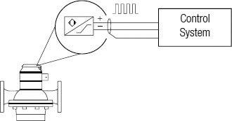
| Flow Calculator | Freely programmable, with analog output 4 - 20mA, indication of flow rate, limiting values |
92439 |
|
| Differential Flow Calculator | Freely programmable, with analog output 4 - 20mA, indication of flow rate, limiting values. Both inputs can be read out individually. |
92440 |
|
| Frequency Current Converter | Freely Programmable |
92439 |
|
| Mounting Kit | Kit | For Wall Mounting or on DIN-35mm Rail |
on request |
Contoil – The World's Most Frequently Used Oil Consumption Meter
Leading manufacturers of oil burners and operators of heating systems, ships or diesel engines rely on Contoil fuel oil meters - and with good reasons.
Advantages of Contoil Fuel Oil Meters – Your Benefits
- Optimal Solutions for Every Application
- Simple Burner Setting with Flow Rate Display (Types VZF II)
- Simple Consumption Monitoring with Limiting Value Switch Qmin / Qmax (Types VZF II)
- Manual Dosing Feature, with a Resettable Counter (Types VZF II)
- Can be Mounted on the Pressure or Suction Side of a Pump
- Space-saving Installation – No Straight Inlet / Outlet Sections Required
- Flexible Mounting of the Meter in Horizontal, Vertical or Inclined Positions
- Accurate Measurement Result, since the Reading is Independent of the Temperature and Viscosity of the Fluid
- Minimum Failure Costs due to Simple Function Monitoring, Rapid Fault Analysis and the possibility of Simple Repairs On-site
Areas of Application
- Measure Heating Fuel Consumption by Oil Burners (for example, Heating Boilers, Industrial Furnaces, Tar Processing Plants, Ships' Boilers)
- Measure Propellant Fuel Consumption by Motors and Engines (such as Diesel Locomotives, Construction Machinery, Ships, Emergency Power Units, Combined Heating and Power Stations)
- Consumption Monitoring and Optimization
- Flow Measurement for Mineral Oils
- Optional Remote Processing and Integration into Superior Systems
- Manual Dosing / Batching
- Flow Measurement for Machine and Motor / Engine Oils
- Engine Test Benches
Fuel Types
- Heating Fuel – Extra Light, Light, Medium, Heavy
- Naphtha
- Diesel
- Petrol and Other Lubricating Liquids
See also - METER DATA • PRESSURE DROP CURVES
Download Contoil VZF II 2017 Oil Meters PDF Brochure • Download Maintenance Manual • Visit Aquametro