
ISTEC CORPORATION
Flow Measurement & Control
5 Park Lake Road, Unit 6
Sparta, NJ 07871 USA
Tel 973-383-9888
Fax 973-383-9088
Email
![]()
Newsletter Sign-up Here
OFFICE HOURS
We will be closed on May 24th and May 27th, 2019 in observation of Memorial Day.
We will open again on Tuesday May 28th, 2019
Remember our troops in your prayers as they keep us safe on this Memorial Day.
We Accept
![]()
Last Update:
B38 Series Commercial & Industrial Gas Regulator
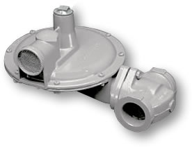 Appropriate for large capacity commercial and industrial uses where inches of water column or pounds delivery is desired such as utility services, gas engines, burner trains, furnaces, and boilers. The rapid response of the B38 is particularly well suited for applications where sudden on/off loads could cause shock problems.
FEATURES
|
BENEFITS
|
B38N |
a spring-loaded, self-operated regulator with no internal relief (N) valve. This model can be used on low or intermediate inlet pressures where an internal relief, or other type of over-pressure protection device is not required. |
B38R |
The internal relief (R) version of the B38 Series. The large 2-1/2" internal relief valve provides exceptional relief capacity. |
B38M |
Used in a series monitoring installation as the upstream regulator. The B38M has an O-ring seal on the valve stem through the throat and a 1/2" control line tap on the lower diaphragm case. |
B38IMN |
Equipped with an Internal Monitoring (IM) device and no internal relief valve (N). This version is appropriate for applications where overpressure protection is desired without the relief of gas to the atmosphere. |
B38IMR |
Equipped with an Internal Monitoring (IM) device as well as a back-up Internal Relief Valve (R). This version is appropriate for applications where an added level of overpressure protection is desired. |
B38IMRV |
Equipped with an Internal Monitoring (IM) device as well as a back-up Internal Relief Valve (R) and a Vent (V) hole in the sliding orifice. The Vent hole option allows the relief valve to "weep" gas to the atmosphere and signal a problem with the regulator in the event the Internal Monitor comes into operation. |
OPTION DESIGNATIONS |
|
N |
No Internal Relief |
R |
Internal Relief |
MN |
Closed Throat with Control Line Tap and No Internal Relief |
MR |
Closed Throat with Control Line Tap and Internal Relief Valve |
IMN |
Internal Monitor with No Internal Relief |
IMR |
Internal Monitor with Internal Relief |
IMRV |
Internal Monitor with Internal Relief and Vent |
USED IN SERIES
|
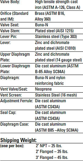 |


MATERIAL CONSTRUCTION
| Valve Body | High Tensile Strength Cast Iron (ASTM A-126, Class A) |
| Valve Seat | Buna-N |
| Valve Stem | Plated Steel (AISI 1215) |
| Lever Pin | Stainless Steel (Type 303) |
| Lever | Zinc and Dichromate-plated Steel (AISI C1010) |
| Upper Diaphragm Plate | Zinc and Dichromate-plated Steel (14 gage steel) |
| Lower Diaphragm Plate | Die Cast Aluminum (ASTM B-85 Alloy SC84A) |
| Diaphragm | Buna-N and Nylon Reinforcing Fabric |
| Vent Valve/Seat | Neoprene |
| Vent Screen | Stainless Steel (16 mesh) |
| Adjustment Ferrule | Delrin; Die Cast Aluminum (ASTM CS43A) |
| Seal Cap | Die Cast Aluminum (ASTM CS43A) |
| Diaphragm Case | Die Cast Aluminum (ASTM B85 –Alloy SC84A) |
| Shipping Weight 2" NPT – 25 lbs. 2" Flanged – 35 lbs. 3" Flanged – 45 lbs. |
1 Regulator per Box |
Correction Factors for Non-Natural Gas Applications
The B31 may be used to control gases other than natural gas. To determine the capacity of the B31 for gases other than natural gas, it will be necessary to multiply the values within the capacity tables by a correction factor. The table below lists the correction factors for some of the more common gases...
| GAS TYPE | SPECIFIC GRAVITY | CORRECTION FACTOR (CF) |
| Air | 1.0 |
0.77 |
| Butane | 2.01 |
0.55 |
| Carbon Dioxide (dry) | 1.52 |
0.63 |
| Carbon Monoxide (dry) | 0.97 |
0.79 |
| Natural Gas | 0.60 |
1.00 |
| Nitrogen | 0.97 |
0.79 |
| Propane | 1.53 |
0.63 |
| Propane Air-mix | 1.20 |
0.71 |
To calculate the Correction Factor for gases not listed in the above Table, it will be necessary to know the Specific Gravity of the Gas and use it in the formula...
Correction Factor (CF) =
Where...
SG1 = Specific Gravity of the gas in which the capacity is published.
SG2 = Specific Gravity of the gas to be controlled.
SPRING RANGE DATA – MODELS N, R, M, D
B38 - ADJUSTED OUTLET PRESSURE RANGE
SPRING ADJUSTMENT FERRULE AT MIN. AND MAX. DEPTHS

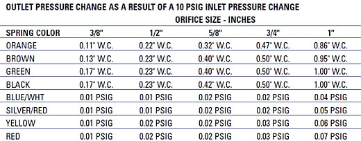
OUTLET PRESSURE CHANGE AS A RESULT OF A 10 PSIG INLET PRESSURE CHANGE – Orifice Size in Inches

ORIFICE DATA: Wide Open Orifice Coefficients and Maximum Pressure Data


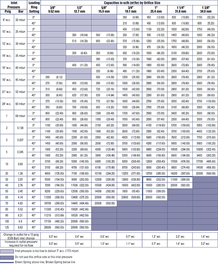
7" (17 mbar)
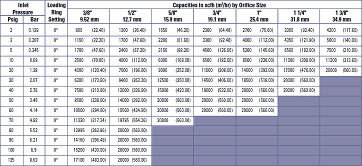
Capacity Table (1" Droop) - Models N, R, DN, DR, MN, MR
Set Point: 7" w.c. (17.5 mbar) @ 200 scfh (5.68 m3/h) Valve Body: 2" x 2" NPT
Green Spring - Part No. 762353 Mounting Position 11
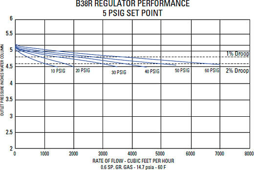
| TYPICAL PERFORMANCE CURVES Type and Model: B38 R Regulator: Inlet Size: 2" NPT Outlet Size: 2" NPT Orifice Size: 1/4" x 3/8" Spring: Green Set Point 7.0" w.c. with 40 psig inlet @ 200 scfh. All test results are reported at a base of 14.7 psia and 60°F |
 |
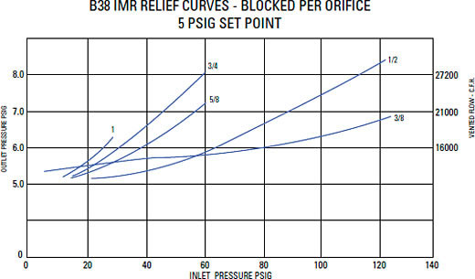
| RELIEF CHATACTERISTIC CURVES - R MODEL ONLY Type and Model: B38 R Regulator: Inlet Size: 2" NPT Outlet Size: 2" NPT Vent Size: 2-1/2" NPT Set Point 7.0" w.c. with 40 psig inlet @ 200 scfh. All test results are reported at a base of 14.7 psia and 60°F |
 |
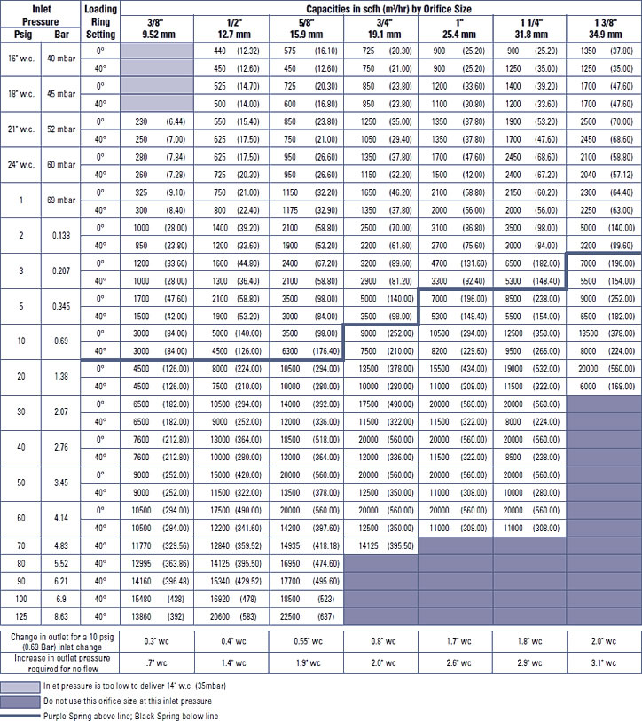
14" (34 mbar)
Capacity Table (2" Droop) - Models N, R, DN, DR, MN, MR
Set Point: 14" w.c. (35 mbar) @ 50 scfh (1.42 m3/h) Valve Body: 2" x 2" NPT
Purple Spring - Part No. 762323 Black Spring - Part No.762355 Mounting Position 11
| TYPICAL PERFORMANCE CURVES Type and Model: B38 R Regulator: Inlet Size: 2" NPT Outlet Size: 2" NPT Orifice Size: 1/4" x 3/8" Spring: Green Set Point 7.0" w.c. with 40 psig inlet @ 200 scfh. All test results are reported at a base of 14.7 psia and 60°F |
 |
| RELIEF CHATACTERISTIC CURVES - R MODEL ONLY Type and Model: B38 R Regulator: Inlet Size: 2" NPT Outlet Size: 2" NPT Vent Size: 2-1/2" NPT Set Point 7.0" w.c. with 40 psig inlet @ 200 scfh. All test results are reported at a base of 14.7 psia and 60°F |
 |
1 psig (69 mbar)
Capacity Table (1% absolute Droop) - Models N, R, DN, DR, MN, MR
Set Point: 1 psig (69 mbar) @ 200 scfh (5.68 m3/h) 2" X 2" NPT Valve Body
Blue/White Spring - Part No. 762358 Mounting Position 11
1 psig (69 mbar)
Capacity Table (2% absolute Droop) - Models N, R, DN, DR, MN, MR
Set Point: 1 psig (69 mbar) @ 200 scfh (5.68 m3/h) 2" X 2" NPT Valve Body
Blue/White Spring - Part No. 762358 Mounting Position 11

| TYPICAL PERFORMANCE CURVES Type and Model: B38 R Regulator: Inlet Size: 2" NPT Outlet Size: 2" NPT Orifice Size: 1/4" x 3/8" Spring: Green Set Point 7.0" w.c. with 40 psig inlet @ 200 scfh. All test results are reported at a base of 14.7 psia and 60°F |
 |
| RELIEF CHATACTERISTIC CURVES - R MODEL ONLY Type and Model: B38 R Regulator: Inlet Size: 2" NPT Outlet Size: 2" NPT Vent Size: 2-1/2" NPT Set Point 7.0" w.c. with 40 psig inlet @ 200 scfh. All test results are reported at a base of 14.7 psia and 60°F |
 |
2 psig (138 mbar) Capacity Table (1" Droop) - Models N, R, DN, DR, MN, MR
Set Point: 2 psig (138 mbar) @ 200 scfh (5.68 m3/h) 2" x 2" NPT Valve Body
Silver Spring - Part No. 762359 Mounting Position 11

2 psig (138 mbar) Capacity Table (1" Droop) - Models N, R, DN, DR, MN, MR
Set Point: 2 psig (138 mbar) @ 200 scfh (5.68 m3/h) 2" x 2" NPT Valve Body
Silver Spring - Part No. 762359 Mounting Position 11

| TYPICAL PERFORMANCE CURVES Type and Model: B38 R Regulator: Inlet Size: 2" NPT Outlet Size: 2" NPT Orifice Size: 1/4" x 3/8" Spring: Green Set Point 7.0" w.c. with 40 psig inlet @ 200 scfh. All test results are reported at a base of 14.7 psia and 60°F |
 |
| RELIEF CHATACTERISTIC CURVES - R MODEL ONLY Type and Model: B38 R Regulator: Inlet Size: 2" NPT Outlet Size: 2" NPT Vent Size: 2-1/2" NPT Set Point 7.0" w.c. with 40 psig inlet @ 200 scfh. All test results are reported at a base of 14.7 psia and 60°F |
 |
5 psig (345 mbar)
Capacity Table (1% absolute Droop) - Models N, R, DN, DR, MN, MR
Set Point: 5 psig (345 mbar) @ 200 scfh (5.68 m3/h) 2" x 2" NPT Valve Body
Red Nested Spring - Part No. 762671 Mounting Position 11

5 psig (345 mbar)
Capacity Table (2% absolute Droop) - Models N, R, DN, DR, MN, MR
Set Point: 5 psig (345 mbar) @ 200 scfh (5.68 m3/h) 2" x 2" NPT Valve Body
Red Nested Spring - Part No. 762671 Mounting Position 11

| TYPICAL PERFORMANCE CURVES Type and Model: B38 R Regulator: Inlet Size: 2" NPT Outlet Size: 2" NPT Orifice Size: 1/4" x 3/8" Spring: Green Set Point 7.0" w.c. with 40 psig inlet @ 200 scfh. All test results are reported at a base of 14.7 psia and 60°F |
 |
| RELIEF CHATACTERISTIC CURVES - R MODEL ONLY Type and Model: B38 R Regulator: Inlet Size: 2" NPT Outlet Size: 2" NPT Vent Size: 2-1/2" NPT Set Point 7.0" w.c. with 40 psig inlet @ 200 scfh. All test results are reported at a base of 14.7 psia and 60°F |
 |
SPRING RANGE DATA – MODELS B38IMN, B38IMR
Adjusted Outlet Pressure Range
Spring Adjustment Ferrule at Min. and Max. Depths
* Maximum allowable pressure is 5.00 PSIG
INTERNAL MONITOR LOCK-UP AND RELIEF PRESSURE DATA
Main Spring Color |
Outlet Pressure Set Point |
IM Lock-up Pressure Models B38IMN & IMR |
Relief Pressure Model B38IMRV |
BROWN |
5.5" w.c. |
11.0" w.c. |
15.0" w.c. |
BROWN N Models |
7.0 w.c. |
12.5" w.c. |
17.0" w.c. |
GREEN R Models |
7.0" w.c. |
12.5" w.c. |
17.0" w.c. |
BLACK |
11.0" w.c. |
19.0" w.c. |
22.5" w.c. |
BLACK |
14.0" w.c. |
23.5" w.c. |
29.5" w.c. |
BLUE/WHITE |
1 psig |
1.5 psig |
1.9 psig |
SILVER/RED |
2 psig |
3.0 psig |
3.8 psig |
YELLOW |
3 psig |
4.0 psig |
5.0 psig |
RED-NESTED |
5 psig |
6.2 psig |
8.4 psig |
7" (17 mbar)
Capacity Table (1" Droop) - Models IMN, IMR, IMRV
Set Point: 7" w.c. ( mbar) @ 200 scfh (5.68 m3/h) Loading Ring Setting: 27 degrees
2" x 2" NPT Valve Body Green Spring-Part No. 762353 Mounting Position 11

| TYPICAL PERFORMANCE CURVES Type and Model: B38 R Regulator: Inlet Size: 2" NPT Outlet Size: 2" NPT Orifice Size: 1/4" x 3/8" Spring: Green Set Point 7.0" w.c. with 40 psig inlet @ 200 scfh. All test results are reported at a base of 14.7 psia and 60°F |
 |
| RELIEF CHATACTERISTIC CURVES - R MODEL ONLY Type and Model: B38 R Regulator: Inlet Size: 2" NPT Outlet Size: 2" NPT Vent Size: 2-1/2" NPT Set Point 7.0" w.c. with 40 psig inlet @ 200 scfh. All test results are reported at a base of 14.7 psia and 60°F |
 |
7" (17 mbar)
Capacity Table (1" Droop) - Models IMN, IMR, IMRV
Set Point: 7" w.c. ( mbar) @ 200 scfh (5.68 m3/h) Loading Ring Setting: 27 degrees
2" x 2" NPT Valve Body Green Spring-Part No. 762353 Mounting Position 11

1 psig (69 mbar)
Capacity Table (2% absolute Droop) - Models IMN, IMR, IMRV
Set Point: 1 psig (69 mbar) @ 200 scfh (5.68 m3/h) Loading Ring Setting: 0 degrees
2" X 2" NPT Valve Body Blue/White Spring - Part No. 762358 Mounting Position 11

| TYPICAL PERFORMANCE CURVES Type and Model: B38 R Regulator: Inlet Size: 2" NPT Outlet Size: 2" NPT Orifice Size: 1/4" x 3/8" Spring: Green Set Point 7.0" w.c. with 40 psig inlet @ 200 scfh. All test results are reported at a base of 14.7 psia and 60°F |
 |
| RELIEF CHATACTERISTIC CURVES - R MODEL ONLY Type and Model: B38 R Regulator: Inlet Size: 2" NPT Outlet Size: 2" NPT Vent Size: 2-1/2" NPT Set Point 7.0" w.c. with 40 psig inlet @ 200 scfh. All test results are reported at a base of 14.7 psia and 60°F |
 |
2 psig (138 mbar)
Capacity Table (1% absolute Droop) - Models IMN, IMR, IMRV
Set Point: 2 psig (138 mbar) @ 200 scfh (5.68 m3/h) Loading Ring Setting: 0 degrees
2" x 2" NPT Valve Body Silver-Red Spring - Part No. 762323 Mounting Position 11

2 psig (138 mbar)
Capacity Table (2% absolute Droop) - Models IMN, IMR, IMRV
Set Point: 2 psig (138 mbar) @ 200 scfh (5.68 m3/h) Loading Ring Setting: 0 degrees
2" X 2" NPT Valve Body Silver/Red Spring - Part No. 762323 Mounting Position 11

| TYPICAL PERFORMANCE CURVES Type and Model: B38 R Regulator: Inlet Size: 2" NPT Outlet Size: 2" NPT Orifice Size: 1/4" x 3/8" Spring: Green Set Point 7.0" w.c. with 40 psig inlet @ 200 scfh. All test results are reported at a base of 14.7 psia and 60°F |
 |
| RELIEF CHATACTERISTIC CURVES - R MODEL ONLY Type and Model: B38 R Regulator: Inlet Size: 2" NPT Outlet Size: 2" NPT Vent Size: 2-1/2" NPT Set Point 7.0" w.c. with 40 psig inlet @ 200 scfh. All test results are reported at a base of 14.7 psia and 60°F |
 |
5 psig (345 mbar)
Capacity Table (1% absolute Droop) - Models IMN, IMR, IMRV
Set Point: 5 psig (345 mbar) @ 200 scfh (5.68 m3/h) Loading Ring Setting: 0 degrees
2" x 2" NPT Valve Body Red Nested Spring - Part No. 762671 Mounting Position 11
5 psig (345 mbar)
Capacity Table (2% absolute Droop) - Models IMN, IMR, IMRV
Set Point: 5 psig (345 mbar) @ 200 scfh (5.68 m3/h) Loading Ring Setting: 0 degrees
2" x 2" NPT Valve Body Red Nested Spring - Part No. 762671 Mounting Position 11

| TYPICAL PERFORMANCE CURVES Type and Model: B38 R Regulator: Inlet Size: 2" NPT Outlet Size: 2" NPT Orifice Size: 1/4" x 3/8" Spring: Green Set Point 7.0" w.c. with 40 psig inlet @ 200 scfh. All test results are reported at a base of 14.7 psia and 60°F |
 |
| RELIEF CHATACTERISTIC CURVES - R MODEL ONLY Type and Model: B38 R Regulator: Inlet Size: 2" NPT Outlet Size: 2" NPT Vent Size: 2-1/2" NPT Set Point 7.0" w.c. with 40 psig inlet @ 200 scfh. All test results are reported at a base of 14.7 psia and 60°F |
|
MODELS B38IMR, B38IMRV & B38IMN: INTERNAL MONITOR PRINCIPLE OF OPERATION
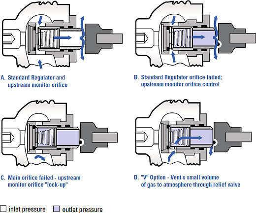
INTERNAL MONITOR PRINCIPLE OF OPERATION
A. The internal monitor (IM) orifice performs like a standard regulator and monitor orifice in that the monitor orifice is wide open under normal operation and the regulating orifice and valve seat actuate to control outlet flow and pressure. The regulator is free to lock-up in the usual manner, with pressure increase to position the valve seat "bubble" tight against the regulating orifice face. However, both the monitor seat and the regulator seat may close together, if the positive shock lockup exceeds the monitor spring setting.
B. If the main valve seat fails to control the gas flow and pressure due to foreign matter between the seat and orifice face, or if the seat is eroded, the internal monitor orifice automatically goes into operating position at a slightly higher outlet pressure. Any time the pressure on the large main diaphragm exceeds the force of the fixed monitor spring and the adjusted pressure of the main spring, this increase in outlet pressure causes the main valve seat to push against the sliding orifice, compressing the monitor spring and positions the monitor orifice to control the gas flow. The IM orifice now functions as a monitor regulator and will continue to monitor so long as the main seats fails to control at the normal adjusted outlet pressure. However, if the gas load demand is increased beyond the Internal Monitor's capacity, the outlet pressure is reduced to normal adjusted pressure and the regulator resumes normal regulation.
C. However, if the demand for gas is decreased to zero flow during monitor operation, the sliding orifice continues to close until its orifice is in the gas tight position (monitor lock-up) against the BUNA-N monitor valve seat.
D. On installations where a small volume of over-pressure gas can be safely vented to atmosphere, the advantage of both relief valve and monitor safety can be combined. The monitor to hold overpressure buildup to a low-pressure increase, and relief gas vented to atmosphere to indicate that the main valve has failed and the regulator is on monitor operation.
LOADING RING ADJUSTMENT INSTRUCTIONS
Function
The purpose of the loading ring (Figure 1) and deflector ring is to draw gas from the underside of the diaphragm. The objective is to lower pressure under the diaphragm as the spring loses compression. The loss in spring compression occurs as the diaphragm drops to open the valve. Lowering of the pressure under the diaphragm relative to the downstream pressure strokes the valve open, thus delivering more gas to the downstream and effectively raising (or boosting) the pressure.
Adjustment
The B38 is equipped with a ported metal loading ring (Figure 1). It is a heat-treated spring steel stamping with two beads (Figure 2) which fit into a groove on the orifice. The orifice also has a radial notched shoulder into which a tip (Figure 2) on the ring rests. This locks the ring from turning after it has been positioned. After removing the diaphragm case from the valve body, remove the loading ring from the orifice by spreading the loading ring slightly with both thumbs (Figure 3). Insert the loading ring on the orifice with the center of the loading ring opening (Figure 1) aligned with the casting seam (Figure 4) on the downstream side. The loading ring is now in the 0° position. The angle between each notch on the B38 orifice is 1.9°. Divide the desired angle (see capacity tables for recommended loading ring position) by 1.9 and round this number up to the nearest whole number (Example: 10.4 = 11 notches). |
 Fig. 1 |
 Fig. 2 |
 Fig. 3 |
 Fig, 4 |
This is the required number of notches the loading ring must be turned. The loading ring may be adjusted either clockwise or counter-clockwise. Using two thumbs as shown in Figure 3, rotate the loading ring the required number of notches. Replace the diaphragm case, slowly open the upstream valve, and check for any leaks. The regulator is now ready for operation.
ASSEMBLY POSITIONS
