
ISTEC CORPORATION
Flow Measurement & Control
5 Park Lake Road, Unit 6
Sparta, NJ 07871 USA
Tel 973-383-9888
Fax 973-383-9088
Email
![]()
Newsletter Sign-up Here
OFFICE HOURS
We will be closed on May 24th and May 27th, 2019 in observation of Memorial Day.
We will open again on Tuesday May 28th, 2019
Remember our troops in your prayers as they keep us safe on this Memorial Day.
We Accept
![]()
Last Update:
 Model RB4000 Gas Regulator
The Series RB4000 Pressure Regulator is designed for gas supply networks, district station regulation, industrial service regulation, and all applications where accurate pressure control, ease of adjustment, and fast response are required such as for burners, industrial ovens, boilers, etc.
FEATURES
|
BENEFITS
|
Body |
– |
Ductile iron quality 500-7 UNI-ISO 1083, Steel quality ASTM A 216 WCB |
Internal Parts |
– |
Brass and Stainless Steel |
Diaphragm |
– |
Synthetic Rubber with Fabric Reinforcement |
Seals |
– |
Nitrile Rubber or Viton (on request) |
Diaphragm Casing & Cover |
– |
UNI/EN 10025 Pressed Steel |

Correction Factors for Non-Natural Gas Applications
The B31 may be used to control gases other than natural gas. To determine the capacity of the B31 for gases other than natural gas, it will be necessary to multiply the values within the capacity tables by a correction factor. The table below lists the correction factors for some of the more common gases...
| GAS TYPE | SPECIFIC GRAVITY | CORRECTION FACTOR (CF) |
| Air | 1.0 |
0.77 |
| Butane | 2.01 |
0.55 |
| Carbon Dioxide (dry) | 1.52 |
0.63 |
| Carbon Monoxide (dry) | 0.97 |
0.79 |
| Natural Gas | 0.60 |
1.00 |
| Nitrogen | 0.97 |
0.79 |
| Propane | 1.53 |
0.63 |
| Propane Air-mix | 1.20 |
0.71 |
To calculate the Correction Factor for gases not listed in the above Table, it will be necessary to know the Specific Gravity of the Gas and use it in the formula...
Correction Factor (CF) =
Where...
SG1 = Specific Gravity of the gas in which the capacity is published.
SG2 = Specific Gravity of the gas to be controlled.Use the table to define the version(s) of the 4000 Pressure Regulator that you wish to order...
* Please specify valve body material on your order (Ductile Iron or Steel).
** Multiply capacity data by 0.7 when using shut-off valve versions.VALUE BODY SIZES


Spring Ranges: 2" Valve Body

Spring Ranges: 3" Valve Body

Over-pressure Shut-off Valve Spring Ranges

Under-pressure Shut-off Valve Spring Ranges

2" RB4010 Capacity Table

2" RB4020 Capacity Table

2" RB4030 Capacity Table

3" RB4020 Capacity Table

3" RB4030 Capacity Table

3" RB4040 Capacity Table


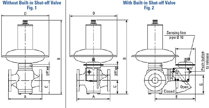
The fluid from the upstream pipe enters the inlet chamber (8), passes through the opening in the valve seat (29) and (7), expands in the outlet chamber (11) and then enters the downstream pipe. The pressure of the gas is sensed downstream via the control line, and passes through the port (13) before entering the control chamber (14). This pressure exerts a force on the surfaces of the diaphragm (15) that balances the calibration spring (2) load for the ideal positioning of the valve plug (10) required to guarantee the requested flow and downstream regulation.
If, during operation, the flow increases due to a greater demand or the upstream pressure decreases, the pressures in the chambers (11) and (14) immediately drop and the calibration spring (2) moves the diaphragm unit (15), the stem (6) and the valve plug (10) downwards, thereby modifying the adjustment position to give the required pressure and flow values.
The reverse action occurs whenever the flow decreases or if the upstream pressure increases. In this case, the pressure regulator's adjustment unit is balanced, and this permits the annulment of any negative forces created because of the change in the pressure upstream in order to guarantee a constant outlet pressure. At zero flow rate, the regulator guarantees full tightness in lock-up.
Shutoff Valve Operation
The shutoff valve is composed of the pressure switch for pressure comparison (23), the control levers (24) and the shut off valve plug (25). The shutoff valve is triggered whenever the pressure in the control chamber (19) increases or decreases beyond the established values. This is achieved when the diaphragm unit (20) moves from the unbalanced position and trips the control levers (24) to release the shutoff valve (25). Under the force generated by the spring (28), the shutoff valve (25) is brought into contact with the valve seat (29) and immediately interrupts the flow of gas.
Monitor Application (See Fig. 5)
The monitor regulator intervenes whenever the main active pressure regulator malfunctions (e.g. fails open), and causes the downstream pressure to rise to the set pressure of the monitor regulator.


