
ISTEC CORPORATION
Flow Measurement & Control
5 Park Lake Road, Unit 6
Sparta, NJ 07871 USA
Tel 973-383-9888
Fax 973-383-9088
Email
![]()
Newsletter Sign-up Here
OFFICE HOURS
We will be closed on May 24th and May 27th, 2019 in observation of Memorial Day.
We will open again on Tuesday May 28th, 2019
Remember our troops in your prayers as they keep us safe on this Memorial Day.
We Accept
![]()
Last Update:
B31 Series Commercial Gas Regulator
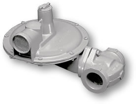 Appropriate for light
commercial and industrial
uses where inches of water
column or pounds delivery is
desired such as utility
services, and small to medium
sized furnaces and boilers.
The rapid response of the B31
is particularly well suited for
applications where sudden
on/off loads could cause
shock problems.
Appropriate for light
commercial and industrial
uses where inches of water
column or pounds delivery is
desired such as utility
services, and small to medium
sized furnaces and boilers.
The rapid response of the B31
is particularly well suited for
applications where sudden
on/off loads could cause
shock problems.
FEATURES
|
BENEFITS
|
B31N |
A spring-loaded, self operated regulator with no internal relief (N) valve. This model can be used on low or intermediate inlet pressures where an internal relief or other type of over-pressure protection device is not required |
B31R |
The internal relief valve (R) version of the B31 Series. The 1" internal relief valve provides exceptional relief capacity. |
B31IMN |
Equipped with an Internal Monitoring (IM) device and no internal relief valve (N). This version is appropriate for applications where overpressure protection is desired without the relief of gas to the atmosphere. |
B31IMR |
Equipped with an Internal Monitoring (IM) device as well as a backup Internal Relief Valve (R). This version is appropriate for applications where an added level of overpressure protection is desired. |
B31IMRV |
Equipped with an Internal Monitoring (IM) device as well as a back-up Internal Relief Valve (R) and a Vent (V) hole in the sliding orifice. The Vent hole option allows the relief valve to "weep" gas to the atmosphere and signal monitor control in the event the main valve fails to control the downstream pressure. |
B31RAS |
Equipped with a Low Pressure Shut-off Valve and Internal Relief. The low- pressure shut-off valve will close if the flow through the regulator exceeds its maximum flow rate (See Capacity Table for shut-off flow values). The internal relief valve will open if the downstream pressure raises approximately 7" w.c. above the regulator's set point. |
OPTION DESIGNATIONS |
|
N |
No Internal Relief |
R |
Internal Relief |
IMN |
Internal Monitor with No Internal Relief |
IMR |
Internal Monitor with Internal Relief |
IMRV |
Internal Monitor with Internal Relief and Vent |
HP |
All Models for Outlet Pressures > 0.5 psig |
RAS |
Internal Relief with Low Pressure Shutoff Valve |
| Valve Body | High Tensile Strength Cast Iron (ASTM A-126, Class A) |
| Orifice | Standard Aluminum or Optional Brass (ASTM B16, Alloy 360) |
| Internal Monitor Orifice | Brass (ASTM B16, Alloy 360) |
| Valve Seat | Buna-N or Silicone (for Temperatures below -20°F) |
| Valve Stem | Plated Steel (AISI 1215) |
| Lever Pin | Stainless Steel (Type 303) |
| Lever | Zinc and Dichromate-plated Steel (AISI C1010) |
| Upper Diaphragm Plate | Zinc and Dichromate-plated Steel (14 gage steel) |
| Lower Diaphragm Plate | Die Cast Aluminum (ASTM B-85 Alloy SC84A) |
| Diaphragm | Buna-N and Nylon Reinforcing Fabric |
| Vent Valve/Seat | Neoprene |
| Vent Screen | Stainless Steel (16 mesh) |
| Adjustment Ferrule | Delrin; Die Cast Aluminum for HP version (ASTM CS43A) |
| Seal Cap | Die Cast Aluminum (ASTM CS43A) |
| Diaphragm Case | Die Cast Aluminum (ASTM B85 –Alloy SC84A) |
| Shipping Weight 52 lbs. |
8 Regulators per Box |
Correction Factors for Non-Natural Gas Applications
The B31 may be used to control gases other than natural gas. To determine the capacity of the B31 for gases other than natural gas, it will be necessary to multiply the values within the capacity tables by a correction factor. The table below lists the correction factors for some of the more common gases...
| GAS TYPE | SPECIFIC GRAVITY | CORRECTION FACTOR (CF) |
| Air | 1.0 |
0.77 |
| Butane | 2.01 |
0.55 |
| Carbon Dioxide (dry) | 1.52 |
0.63 |
| Carbon Monoxide (dry) | 0.97 |
0.79 |
| Natural Gas | 0.60 |
1.00 |
| Nitrogen | 0.97 |
0.79 |
| Propane | 1.53 |
0.63 |
| Propane Air-mix | 1.20 |
0.71 |
To calculate the Correction Factor for gases not listed in the above Table, it will be necessary to know the Specific Gravity of the Gas and use it in the formula...
Correction Factor (CF) = [SG1/SG2]1/2
Where...
SG1 = Specific Gravity of the gas in which the capacity is published.
SG2 = Specific Gravity of the gas to be controlled.
SPRING DATA – Spring Color Outlet Pressure Range*
| Model B31 | Part Number |
Outlet Pressure Range Models N, R, & RA inches w.c. (mbar) |
Outlet Pressure Range Models IMN & IMR inches w.c. (mbar) |
| Brown | 762111 |
4.5 to 5.5 (11.2 to 13.7) |
4.5 to 5.5 (11.2 to 13.7) |
| Dark Green | 762117 |
5.0 to 6.5 (12.4 to 16.7) |
5.5 to 6.0 (13.7 to 14.9) |
| Gray | 762139 |
4.0 to 9.0 (9.9 to 22.4) |
4.5 to 8.5 (11.2 to 21.1) |
| Light Green | 762119 |
5.5 to 8.0 (11.2 to 19.9) |
6.0 to 7.5 (14.9 to 18.6) |
| Black | 762123 |
7.3 to 11.0 (18.1 to 27.3) |
6.0 to 9.0 (14.9 to 22.4) |
| Blue | 762127 |
8.0 to 12.0 (19.9 to 29.8) |
7.5 to 11.5 (18.6 to 28.6) |
| Silver | 762129 |
11.0 to 16.0 (27.3 to 39.8) |
8.0 to 14.5 (19.9 to 36.1) |
| Model B31HP** | PSIG (mbar) |
PSIG (mbar) |
|
| Red/Grey | 762025 |
0.75 to 1.1 (51.7 to 75.8) |
0.5 to 1.0 (34.5 to 68.9) |
| Yellow | 762131 |
0.9 to 1.4 (62.0 to 96.5) |
1.0 to 1.5 (68.9 to 103.4) |
| Red | 762135 |
1.3 to 2.0 (89.6 to 137.9) |
1.3 to 1.9 (89.6 to 131.0) |
| White | 762137 |
1.75 to 2.5 (121 to 172) |
1.5 to 2.5 (68.9 to 172.0) |
* Spring Ranges are approximate and may vary by application.
* * Warning: Springs are not interchangeable between B31 and B31HP.
OROFICE DATA – Wide Open Flow Coefficients and Maximum Pressure Data
| Orifice Size | K-Factor (scfh/psi) |
Maximum Operating Inlet Pressure All Models |
Maximum Emergency Inlet Pressure All Models |
Maximum Emergency Outlet Pressure (Gas Containment) |
||
In. W.C. Delivery |
PSIG delivery |
All Outlet |
In. W.C. Delivery |
PSIG Delivery |
||
Pressure PSIG (Bar) |
Pressure PSIG (Bar) |
Pressure PSIG (Bar) |
Pressure PSIG (Bar) |
Pressure PSIG (Bar) |
||
1/8" |
30 |
125 (8.6) |
175 (12.1) |
300 (20.6) |
18 (1.2) |
60 (4.1) |
1/8" IM |
35 |
125 (8.6) |
175 (12.1) |
300 (20.6) |
||
3/16" |
71 |
125 (8.6) |
175 (12.1) |
300 (20.6) |
||
3/16" IM |
68 |
125 (8.6) |
175 (12.1) |
300 (20.6) |
||
1/4" |
127 |
125 (8.6) |
125 (8.6) |
300 (20.6) |
||
1/4" IM |
112 |
125 (8.6) |
125 (8.6) |
300 (20.6) |
||
5/16" |
193 |
100 (6.9) |
100 (6.9) |
150 (10.3) |
||
5/16" IM |
138 |
100 (6.9) |
100 (6.9) |
150 (10.3) |
||
3/8" |
290 |
65 (4.5) |
60 (4.1) |
150 (10.3) |
||
1/2" |
500 |
40 (2.8) |
40 (2.8) |
100 (6.9) |
||
For wide-open orifice flow calculations use the following equations:
| For P1/P2<1.89 use: | For P1/P2>1.89 use: Q = KP1/ 2 | |
| Where: | P1 = absolute inlet pressure (psia) | P2 = absolute outlet pressure (psia) |
| Q = flow rate (scfh) | K = orifice coefficient (scfh/psi) |
VALVE BODY SIZES
Inlet |
Outlet |
Straight Body (NPT) |
Angle Body (NPT) |
1/2" |
3/4" 1" |
X X |
|
3/4" |
3/4" 1" 1-1/4" |
X X X |
X X |
1" |
1" 1-1/4" |
X X |
X |
1-1/4" |
1-1/4" |
X |
|
| X indicates that the Valve Body is available in that configuration | |||
| Available Vent Sizes | 1/4" • 3/8" • 3/4" • 1" | ||
| Operating Temperature Range | -20°F to 150°F (Silicone Seats Available below –20°F) | ||
| Other Available Option | • Seal Wire to Indicate Unapproved Tampering • 1/8" Pipe Plug Tap on Upstream Side of Valve Body • Tamper-Proof (Torx Head) Diaphragm Case Screws |
||
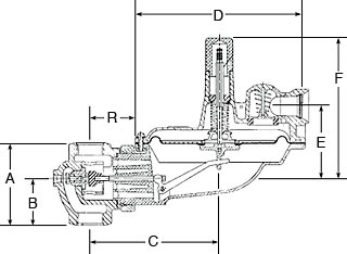
Valve Body Type
A |
B |
C |
D |
E |
F |
R |
|
3/4" & 1" |
3-3/4" |
2-1/8" |
5-13/16" |
7-13/16" |
3-1/4" |
4-7/8" |
2-1/4" |
1-1/4" |
4" |
2-1/8" |
5-13/16" |
7-13/16" |
3-1/4" |
4-7/8" |
2-1/4" |
3/4" & 1" 90° Angle Body |
1-5/8" |
5-13/16" |
7-13/16" |
3-1/4" |
4-7/8" |
2-1/4" |
|
7" w.c. (17 mbar) Set Point Capacity Table (1" Droop)
Models N, R*
(capacities in SCFH of 0.6 S.G. gas; Base condition of 14.7 psia and 60°F)
Inlet Pressure (psig) |
ORIFICE SIZES |
|||||
1/8" |
3/16" |
1/4" |
5/16" |
3/8" |
1/2" |
|
8" w.c. |
100 |
130 |
190 |
270 |
||
10" w.c. |
110 |
160 |
240 |
300 |
||
12" w.c. |
100 |
115 |
165 |
250 |
310 |
|
14" w.c. |
110 |
170 |
190 |
330 |
440 |
|
16" w.c. |
120 |
180 |
205 |
340 |
450 |
|
21" w.c. |
130 |
230 |
255 |
410 |
575 |
|
24" w.c. |
90 |
150 |
230 |
275 |
420 |
585 |
1 |
110 |
160 |
270 |
340 |
560 |
640 |
2 |
150 |
255 |
450 |
560 |
845 |
1120 |
3 |
190 |
325 |
560 |
770 |
1090 |
1470 |
5 |
260 |
470 |
830 |
1050 |
1400 |
1750 |
10 |
400 |
870 |
1470 |
1950 |
2200 |
2400 |
20 |
580 |
1020 |
1670 |
2120 |
2560 |
2650 |
30 |
700 |
1900 |
2550 |
2600 |
2680 |
2700 |
40 |
910 |
2300 |
2600 |
2630 |
2750 |
2760 |
50 |
1070 |
2370 |
2610 |
2670 |
2890 |
|
60 |
1150 |
2420 |
2700 |
2720 |
2930 |
|
70 |
1340 |
2500 |
2750 |
2770 |
||
80 |
1490 |
2510 |
2750 |
2790 |
||
90 |
1640 |
2510 |
2750 |
2790 |
||
100 |
1890 |
2520 |
2770 |
2790 |
||
125 |
2305 |
3420 |
2820 |
|||
| Do not operate orifice in shaded inlet pressure area | ||||||
| Inlet Pressure is too low to achieve desired outlet pressure | ||||||
Increased Pressure Above Set Point Required for No Flow |
||||||
Orifice |
1/8" |
3/16" |
1/4" |
5/16" |
3/8" |
1/2" |
Pressure |
0.3" w.c. |
0.5" w.c. |
0.6" w.c. |
0.8" w.c. |
0.9" w.c. |
1.0" w.c. |
Change in Outlet Pressure with a 10 psig Change in Inlet Pressure |
||||||
Orifice |
1/8" |
3/16" |
1/4" |
5/16" |
3/8" |
1/2" |
Pressure |
0.1" w.c. |
0.2" w.c. |
0.3" w.c. |
0.3" w.c. |
0.4" w.c. |
0.5" w.c. |
| TYPICAL PERFORMANCE CURVES 7" w.c. Set Point Type and Model B-31 R Regulator: Inlet Size 1-1/4" NPT Outlet Size 1-1/4" NPT Orifice Size 1/4" |
RELIEF CURVES - LEVER DISCONNECT 7" w.c. Set Point Type and Model B-31 R Regulator: Inlet Size 3/4" NPT Outlet Size 1" NPT Vent Size 1" NPT |

14" w.c. (34 mbar) Set Point Capacity Table (2" Droop)
Models N, R*
(capacities in SCFH of 0.6 S.G. gas; Base condition of 14.7 psia and 60°F)
Inlet Pressure (psig) |
ORIFICE SIZES |
|||||
1/8" |
3/16" |
1/4" |
5/16" |
3/8" |
1/2" |
|
16" w.c. |
90 |
130 |
170 |
185 |
260 |
|
21" w.c. |
70 |
110 |
150 |
190 |
205 |
305 |
24" w.c. |
80 |
120 |
160 |
225 |
225 |
340 |
1 |
100 |
145 |
200 |
240 |
290 |
410 |
2 |
120 |
210 |
300 |
380 |
475 |
630 |
3 |
155 |
270 |
375 |
500 |
580 |
820 |
5 |
210 |
380 |
560 |
660 |
800 |
1100 |
10 |
350 |
575 |
820 |
1000 |
118- |
1500 |
20 |
510 |
810 |
1240 |
1300 |
1700 |
1550 |
30 |
615 |
1100 |
1500 |
1450 |
1550 |
1400 |
40 |
790 |
1350 |
1740 |
1550 |
1400 |
1300 |
50 |
1000 |
1530 |
1820 |
1500 |
1450 |
|
60 |
1100 |
1950 |
1760 |
1400 |
1350 |
|
70 |
1300 |
2030 |
1650 |
1350 |
||
80 |
1350 |
2080 |
1600 |
1300 |
||
90 |
1450 |
`860 |
1530 |
1275 |
||
100 |
1520 |
2010 |
1580 |
|||
| Do not operate orifice in shaded inlet pressure area | ||||||
| Inlet Pressure is too low to achieve desired outlet pressure | ||||||
Increased Pressure Above Set Point Required for No Flow |
||||||
Orifice |
1/8" |
3/16" |
1/4" |
5/16" |
3/8" |
1/2" |
Pressure |
0.4" w.c. |
0.6" w.c. |
0.7" w.c. |
0.9" w.c. |
0.9" w.c. |
0.9" w.c. |
Change in Outlet Pressure with a 10 psig Change in Inlet Pressure |
||||||
Orifice |
1/8" |
3/16" |
1/4" |
5/16" |
3/8" |
1/2" |
Pressure |
0.1" w.c. |
0.2" w.c. |
0.3" w.c. |
0.4" w.c. |
0.5" w.c. |
0.6" w.c. |
| TYPICAL PERFORMANCE CURVES 14" w.c. Set Point Type and Model B-31 R Regulator: Inlet Size 3/4" NPT Outlet Size 1" NPT Orifice Size 3/16" |
RELIEF CURVES - LEVER DISCONNECT 14" w.c. Set Point Type and Model B-31 R Regulator: Inlet Size 3/4" NPT Outlet Size 1" NPT Vent Size 1" NPT |

1 psig (69 mbar) Set Point Capacity Table (1% Absolute Droop)
Models N, R*
(capacities in SCFH of 0.6 S.G. gas; Base condition of 14.7 psia and 60°F)
Inlet Pressure (psig) |
ORIFICE SIZES |
|||||
1/8" |
3/16" |
1/4" |
5/16" |
3/8" |
1/2" |
|
2 |
120 |
200 |
230 |
310 |
360 |
480 |
3 |
160 |
250 |
330 |
420 |
480 |
640 |
5 |
190 |
360 |
490 |
580 |
670 |
880 |
8 |
230 |
480 |
670 |
780 |
890 |
1260 |
10 |
310 |
550 |
730 |
900 |
1050 |
1370 |
15 |
410 |
690 |
980 |
1170 |
1350 |
1810 |
20 |
500 |
830 |
1150 |
1400 |
1600 |
2100 |
30 |
640 |
1120 |
1520 |
1760 |
2060 |
2150 |
40 |
780 |
1560 |
1920 |
2160 |
2280 |
2300 |
50 |
950 |
1610 |
2170 |
2360 |
2380 |
|
60 |
1100 |
1800 |
2360 |
2530 |
2550 |
|
75 |
1340 |
1960 |
2500 |
2680 |
||
85 |
1510 |
2550 |
2850 |
2810 |
||
100 |
1760 |
2870 |
3010 |
3100 |
||
| Do not operate orifice in shaded inlet pressure area | ||||||
Increased Pressure Above Set Point Required for No Flow |
||||||
Orifice |
1/8" |
3/16" |
1/4" |
5/16" |
3/8" |
1/2" |
Pressure |
0.04 psi |
0.04 psi |
0.04 psi |
0.06 psi |
0.06 psi |
0.06 psi |
Change in Outlet Pressure with a 10 psig Change in Inlet Pressure |
||||||
Orifice |
1/8" |
3/16" |
1/4" |
5/16" |
3/8" |
1/2" |
Pressure |
0.01 psig |
0.02 psig |
0.02 psig |
0.03 psig |
0.03 psig |
0.04 psig |
1 psig (69 mbar) Set Point Capacity Table (2% Absolute Droop)
Inlet Pressure (psig) |
ORIFICE SIZES |
|||||
1/8" |
3/16" |
1/4" |
5/16" |
3/8" |
1/2" |
|
2 |
150 |
300 |
420 |
550 |
660 |
880 |
3 |
200 |
370 |
550 |
730 |
860 |
1190 |
5 |
250 |
540 |
770 |
990 |
1220 |
1630 |
8 |
330 |
700 |
1030 |
1360 |
1640 |
2200 |
10 |
370 |
800 |
1200 |
1560 |
1900 |
2410 |
15 |
470 |
1030 |
1600 |
2020 |
2380 |
3100 |
20 |
550 |
1250 |
1900 |
2420 |
2920 |
2400 |
30 |
700 |
1610 |
2490 |
3080 |
3300 |
3400 |
40 |
860 |
1980 |
3100 |
3420 |
4140 |
4200 |
50 |
1010 |
2300 |
3500 |
3640 |
4300 |
|
60 |
1170 |
2680 |
3680 |
3940 |
4350 |
|
75 |
1400 |
2940 |
3290 |
4220 |
||
85 |
1600 |
3480 |
4250 |
4500 |
||
100 |
1820 |
3930 |
4600 |
4600 |
||
| Do not operate orifice in shaded inlet pressure area | ||||||
| TYPICAL PERFORMANCE CURVES 1 PSIG SET POINT Type and Model B-31 R Regulator: Inlet Size 3/4" NPT Outlet Size 1" NPT Orifice Size 3/16" |
RELIEF CURVES - LEVER DISCONNECT 1 PSIG Set Point Type and Model B-31 R Regulator: Inlet Size 3/4" NPT Outlet Size 1" NPT Vent Size 1" NPT |

2 psig (138 mbar) Set Point Capacity Table (1% Absolute Droop)
Models N, R*
(capacities in SCFH of 0.6 S.G. gas; Base condition of 14.7 psia and 60°F)
Inlet Pressure (psig) |
ORIFICE SIZES |
|||||
1/8" |
3/16" |
1/4" |
5/16" |
3/8" |
1/2" |
|
3 |
100 |
120 |
190 |
210 |
230 |
280 |
5 |
140 |
160 |
260 |
320 |
350 |
450 |
10 |
250 |
290 |
500 |
550 |
600 |
700 |
20 |
450 |
500 |
800 |
900 |
1000 |
1200 |
30 |
550 |
600 |
1000 |
1200 |
1200 |
1400 |
40 |
650 |
800 |
1200 |
1300 |
1500 |
1600 |
50 |
800 |
900 |
1400 |
1600 |
1700 |
|
60 |
900 |
1100 |
1500 |
1700 |
1700 |
|
70 |
955 |
1150 |
1600 |
1700 |
||
80 |
1100 |
1250 |
1700 |
1700 |
||
90 |
1250 |
1320 |
1700 |
1700 |
||
100 |
1400 |
1400 |
1700 |
1700 |
||
125 |
1600 |
1700 |
1700 |
|||
| Do not operate orifice in shaded inlet pressure area | ||||||
Increased Pressure Above Set Point Required for No Flow |
||||||
Orifice |
1/8" |
3/16" |
1/4" |
5/16" |
3/8" |
1/2" |
Pressure |
0.04 psi |
0.05 psi |
0.05 psi |
0.06 psi |
0.06 psi |
0.06 psi |
Change in Outlet Pressure with a 10 psig Change in Inlet Pressure |
||||||
Orifice |
1/8" |
3/16" |
1/4" |
5/16" |
3/8" |
1/2" |
Pressure |
0.01 psig |
0.02 psig |
0.03 psig |
0.04 psig |
0.05 psig |
0.06 psig |
2 psig (138 mbar) Set Point Capacity Table (2% Absolute Droop)
Inlet Pressure (psig) |
ORIFICE SIZES |
|||||
1/8" |
3/16" |
1/4" |
5/16" |
3/8" |
1/2" |
|
3 |
120 |
200 |
320 |
400 |
480 |
530 |
5 |
190 |
330 |
500 |
600 |
700 |
850 |
10 |
280 |
550 |
800 |
1000 |
1100 |
1320 |
20 |
550 |
900 |
1300 |
1500 |
1800 |
2000 |
30 |
700 |
1100 |
1700 |
2000 |
2100 |
2300 |
40 |
800 |
1400 |
2000 |
2300 |
2300 |
2700 |
50 |
1100 |
1700 |
2400 |
2500 |
2500 |
|
60 |
1100 |
2000 |
2500 |
2620 |
2700 |
|
70 |
1125 |
2100 |
2600 |
2850 |
||
80 |
1300 |
2150 |
2800 |
2940 |
||
90 |
1475 |
2250 |
2800 |
3000 |
||
100 |
1700 |
2250 |
2810 |
3060 |
||
125 |
2100 |
2420 |
2980 |
|||
| Do not operate orifice in shaded inlet pressure area | ||||||
| TYPICAL PERFORMANCE CURVES 2 PSIG SET POINT Type and Model B-31 R Regulator: Inlet Size 3/4" NPT Outlet Size 1" NPT Orifice Size 3/16" |
RELIEF CURVES - LEVER DISCONNECT 2 PSIG Set Point Type and Model B-31 R Regulator: Inlet Size 3/4" NPT Outlet Size 1" NPT Vent Size 1" NPT |

See the PDF for more information on Model B31IMR, B31IMRV, and B31IMN, Internal Monitor(IM) Principle of Operation